Wednesday, December 9, 2015
Final design and results
.
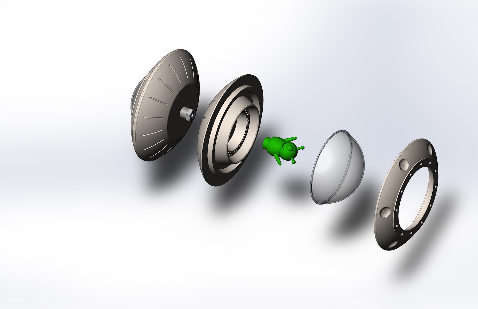
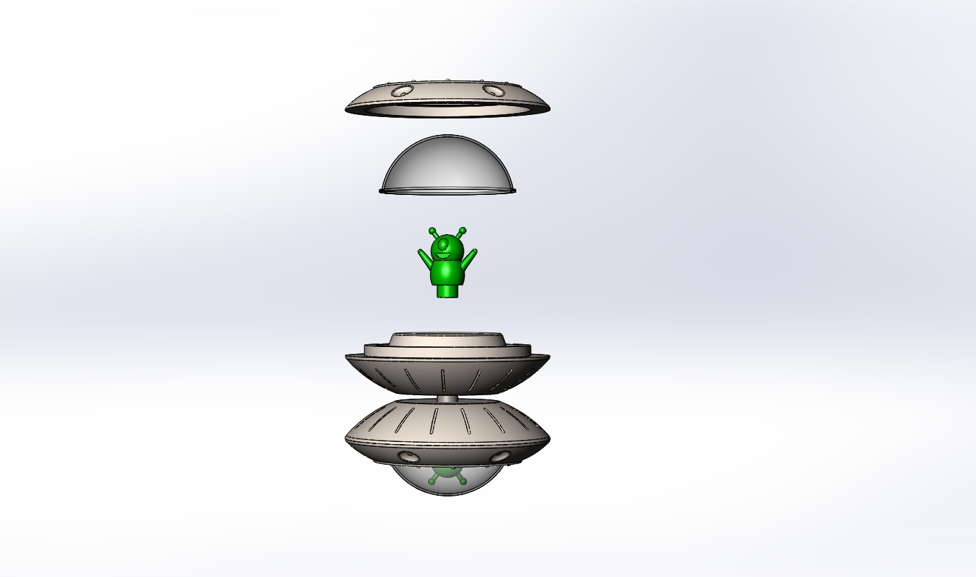
Our team decided on a UFO themed yoyo for our design. The yoyo consists of 4 components: an injection molded base, an injection molded top ring, a friendly injection molded alien, and a thermoformed dome. These 4 components make up half the yoyo, or one UFO. Another UFO is attached with a set screw, an axle spacer, and two embedded hex nuts. Adding a 44in string completes the yoyo.
The silver base makes up the most mass of the yoyo, and makes contact with all three of the other parts. The top ring snap fits around the outermost ridge of the base, and the alien snap fits inside the center hole. There is also a groove where the thermoformed dome fits during assembly. Other aesthetic features of note are the keyboard and the outer ridges. The alien’s keyboard was made using precise machining with a 1/32” end mill and the outer ridges required 3D machining to manufacture, which also produced tiny radial lines that resemble metal sheeting and help hide the injection molding weld line.
The top ring snap fits onto the base, has the same outer diameter, and is the same color, making the two look like one part. The outer diameter of the ring and base are curved to eliminate a sharp edge and make the yoyo more comfortable to hold. The 12 small protruding bumps on the top were machined with a 1/16” drill. The 6 larger holes on the outside were made using 3D machining, which like the base also produced tiny radial lines. Other than these aesthetic and textual features, the top ring also serves to securely lock the dome into place. We dimensioned the inner diameter of the ring to fully constrain the dome when assembled. This in addition to a very tight snap fit required us to use an arbor press to fit the ring onto the base.
For the alien we used trial and error to find the right mixture of green and glow in the dark plastic, and ultimately produced a nice light green. He appears to be very friendly from inside the UFO, literally greeting the world with a smile and open arms. We made sure that the antennae, the most fragile part of the yoyo, are short enough to avoid contact with the dome. The snap fit between the alien and base is also extremely tight, making up for it only being 0.1 inch deep. The alien mold was produced exclusively with 3D machining, which was necessary to make the odd shape. The mold produces two aliens per injection molding cycle, reducing production time.
Finally, the clear dome is the last component of the yoyo. It was produced by thermoforming and is pinned in place between the top ring and base. Despite being made of thin plastic, it is extremely structurally solid due to its spherical shape. It’s not possible for a person to bend it with his bare hands, and we have yet to see it affected by being thrown on the ground. In this way it serves to protect the relatively fragile alien on the inside.

The two snap fits of our yoyo are both extremely tight. We were forced to use an arbor press for the ring fit, and we developed a special metal tool to press the alien without harming its antennae. While this increased assembly time, it made our yoyo exceedingly robust. We can forcefully throw in on the ground several times before it comes apart. Also, our design protects our most fragile part inside the other three.

We are very happy with our final product. Our UFO-yo is attractive, comfortable to use, and durable. By utilizing 3D machining, we could produce interesting features and parts that help distinguish our yoyo from the norm, and also help hide our weld lines. The tight snap fits and strong dome make our yoyo exceptionally resilient to wear and impact. Because of all this, we believe our yoyo is truly out of this world.
Final Specifications
|
Comparison of Initial and Final Critical
Dimensions
|
||||
|
Location
|
Average
Final Value [in]
|
Initial
Value [in]
|
Difference
(Final-Initial)
|
|
|
Max
Diameter of UFO
|
2.495
|
2.461
|
0.034
|
|
|
OD
of Snap Fit
|
2.004
|
1.990
|
0.014
|
|
|
ID
of Snap Fit
|
2.031
|
2.000
|
0.031
|
|
|
Alien
Height
|
0.688
|
0.68*
|
.008
|
|
|
Alien
ID Snap Fit
|
0.256
|
0.260
|
-0.004
|
|
|
Base
UFO OD Snap Fit
|
0.248
|
0.250
|
-0.002
|
|
|
Height
of Dome
|
0.694
|
0.688
|
0.006
|
|
|
Width
of Dome
|
1.623
|
1.580
|
0.043
|
|
|
String
Gap
|
0.09
|
0.100
|
-0.01
|
|
|
Total
Width of Yoyo Half
|
1.161
|
1.138
|
0.023
|
|
|
Total
Mass
|
65.1
[g]
|
64.68
[g]
|
.44
[g]
|
|
|
Maximum Rotation Speed
|
~2500 rpm (measured)
|
1271.4 rpm (estimated)
|
1228.6 rpm
|
|
|
Tolerances
|
Final
Tolerances (all tolerances not listed here are +/-.0075)
Note: Dome width tolerance:+/-.025
|
Initial
Tolerances (all tolerances not listed here are +/-.005)
|
||
|
Location
|
(+)
Value [in]
|
(-)
Value [in]
|
(+)
Value [in]
|
(-)
Value [in]
|
|
OD
of Snap Fit
|
0.005
|
0.005
|
0.005
|
0.0
|
|
ID
of Snap Fit
|
0.005
|
0.005
|
0.0
|
0.005
|
|
Alien
ID Snap Fit
|
0.005
|
0.005
|
0.0
|
0.005
|
|
Base
UFO OD Snap Fit
|
0.005
|
0.005
|
0.005
|
0.0
|
Each dimension was adjusted slightly through the design and manufacturing process. The measurement that were not measured on all 110 parts were measured on a random selection of 10 parts. The numbers presented here are averages of the collected measurements. Below is an explanation for the change in each dimension.
Max Diameter of UFO
Upon inspecting the parts, it is clear that the top part tends to jut out slightly more on the bottom part. There are two likely causes for this. The first with a lesser contribution, is the minimal shrinkage of the outer diameter of the top part, when slight dishing occurs on the sloped side of the ring. In addition to the slightly increased mold size to accommodate for shrinkage, the top ring may be slightly larger than the bottom ring that is more prone to shrinkage with such a large mass. More importantly however, is the significant interference of the snap fit, an average close to .03 inches. This could make the thin top ring stretch and flare outwards, accounting for the increased total diameter.
OD and ID of Snap Fit
In initial testing runs, the snap fit was far too loose. It could be pried apart by hand and did not stay assembled when dropped. Initial steps taken were to increase the interference. This helped but it still did not remain assembled when dropped. We decided to add an undercut to the snap fits. We then discovered that the mold for the top ring had what was most likely a draft angle on the snap fit. When this was removed in addition to the undercut and the increased interference, we had a significant interference that required an arbor press to assemble. This was the process that led to the parameter change in this dimensions.
Alien height
The alien height was close to the initial parameter. This minor variation is likely the cause of minimal shrinkage when the shrinkage accounted for by the mold was 2%.
Alien ID Snap Fit
This dimension stayed quite close to specifications. The minimal change here is likely due to the choice of Injection Molding parameters.
Base UFO OD Snap Fit
This dimension stayed quite close to specifications. The minimal change here is likely due to the choice of injection molding parameters. Despite the large mass of the UFO and the long cooling time, the OD of the alien snap fit is in a geometry that allows little variation, making shrinkage variation minimal.
Height of Dome
This dimension stayed quite close to specifications. The slight variation may be due to the location where the dome was cut from the thermoform, since a drop gauge was used to measure the height.
Width of Dome
This dimension seems to be extremely far from the specification. However, this is likely a function of measurement method rather than the change of the specification. On the curved surface of the thermoform, it was hard to determine a location that should be measured for the width of the dome. The measurement method we settled on provided relatively consistent results, but perhaps not at the exact location of the width of the thermoform. Other measurements methods were considered. If the dome were die punched, the measurement would be a function of both the variability of the die cut and the dome. In addition, the calipers would squish the pliable thermoform, also causing inconsistency in measurements.
String Gap
This dimension is relatively close to the original dimension. A significant change that took place was that during assembly, we discovered that with a ⅝ inch set screw, the aliens were pushed out of their snap fit. Therefore, a ½ inch set screw was used. This shorter set screw may have allowed for extra tightening, causing the .01 inch change in dimension.
Total Width of Yoyo Half
The slight difference in dimension here is due in part to the dishing on string gap side of the base part. When using the drop gauge, it was apparent that the dishing on that surface was contributing to the total height.
Total Mass
The total mass of the yoyo about half a gram greater. This is likely due to the addition of the set screw, spacer, and string.
Maximum Rotation Speed
The initial calculation assumed that 30% of the energy was lost to friction, and that the initial speed was 1 m/s. After testing the yo-yo, it is clear the the estimated 1 m/s is too low. Considering the yo-yo can easily sleep for about a minute, a 30% energy loss to friction is probably also quite high. Both of these poor approximation could account for the large difference in rpm.
Tolerances
Most tolerances were close to the initial specifications. The tolerances of these parts were determined by calculating 3σ. After performing the calculations, it is clear that the snap fits did not have one-sided tolerances. However for the top and bottom snap fit, the tolerances were almost irrelevant, considering how large the interference was. For the base and the alien, a very large interference was hard to assemble because the geometry of both the base and the alien do not allow for stretching or squishing. In addition, if the parts were only nominally the same size, the fit was not snug enough. In this scenario, the plethora of aliens available to us made it easy to perform what we dubbed “the apple method” which was switch out the alien if the press fit was too challenging, or the alien felt too loose. In addition, for several of the parts with only 10 sample measurements, the tolerance was higher than .005. With a larger data set, the tolerance is expected to drop. In addition, for reasons mentioned in the width of dome section, the dome width had a higher tolerance.Cost Analysis
We ran cost analyses for multiple cases. Here are two of the most interesting cases. Case 1 is a cost analysis for production, showing relative costs of different aspects of manufacturing. Case 3 is the same plot except for mass production through a rented manufacturing line, such as through companies like Protomold.
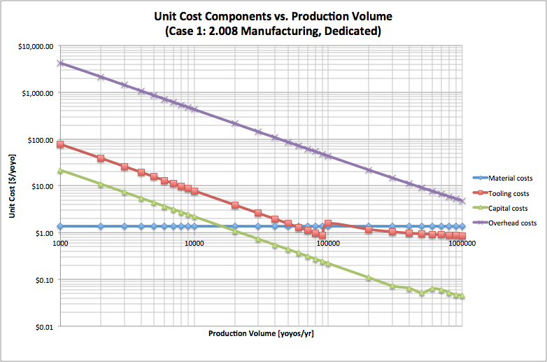 |
| Figure 1: Cost analysis for prototyping in 2.008 |
The first graph confirms that unit cost decreases (very steeply at first, before leveling off) as production volume increases, and the second graph tells us that this relationship is due to drops in the tooling, capital, and overhead costs. The unit material costs remain constant since we are allowed to purchase just the right amount. As our volume increases, the unit tooling cost decreases, which is just what we would expect because the same mold is getting used for more runs. In other words, the cost of making that mold doesn’t increase, but it gets divided by a larger number of produced parts when we calculate the unit cost. At 100,000, however, the tooling cost jumps up for a data sample because we have to pay for the tooling of new mold sets (we assumed mold life of 100,000). The overhead cost is the largest contributor to the total manufacturing cost. It decreases as volume increases because a smaller percentage of the dedicated machines/employees are being paid for “wasted” time. Capital costs decrease with increasing volume because
 |
| Figure 2: Cost analysis for mass production |
As we saw before in case (1), volume has no effect on the material costs; if you make more parts, you need to buy exactly much more material. Here, the overhead costs remain constant at $1.36 per yoyo because Case (3) calls for a rented manufacturing line. This means that employees and machines are both non-dedicated. Since we already don’t pay for any “wasted” time in the overheads at low volume, increasing production volume does not lead to more efficient use of workers and machines. Similarly, capital costs remain constant at $0.04 because the machines are already operating at full capacity. Tooling costs still decrease with increasing production volume; the rented line has no bearing on tooling, because we still need to machine all the mold sets. And then again we can see the little upward “blip” in the downward trend of the tooling cost, specifically at 100,000 yoyos. This is due to the added tooling expenses of making more mold sets for each yoyo part, since we assumed mold life to be 100,000 runs.
Moving towards mass-production
We are overall happy with our final prototype, although there is still room for progress to be made before moving to mass production. We faced some limits with the 2.008 manufacturing equipment, and other limits in the part time effort during one semester.
The largest limit we see with using the 2.008 manufacturing equipment was the predefined mold blanks. We received aluminum blocks with a set sprue location that we had to work around. These were a problem for two reasons. First, aluminum molds are prototype molds and would likely be switched to a more durable metal for mass production. Second, the sprue caused us to flow plastic in from one side of the yoyo to the other, rather than feeding the plastic in from the center. Due to this location, the flow of plastic forms a pressure gradient from one side of the outer diameter to the other, resulting in a density gradient. The final yoyo has an eccentric mass that causes it to wobble. This could be solved by placing the gate at the center point of the yoyo parts.
Another limit was in the ejector pin machinery. We had a list of radially spaced pin locations to choose from, but in the case of the alien, this was a problem. We changed the location and number of the aliens in the mold to accommodate this, as seen in the above mold configurations.


In addition, the thermoforming setup was a limit towards mass production. We had plastic blanks that only allowed for one dome to be formed at a time. In mass production, we would likely build much larger tooling to work on a larger thermoforming machine, or even one that allowed for a constant automated line, in order to build more parts in the same amount of time.
Friday, November 20, 2015
Molds!!
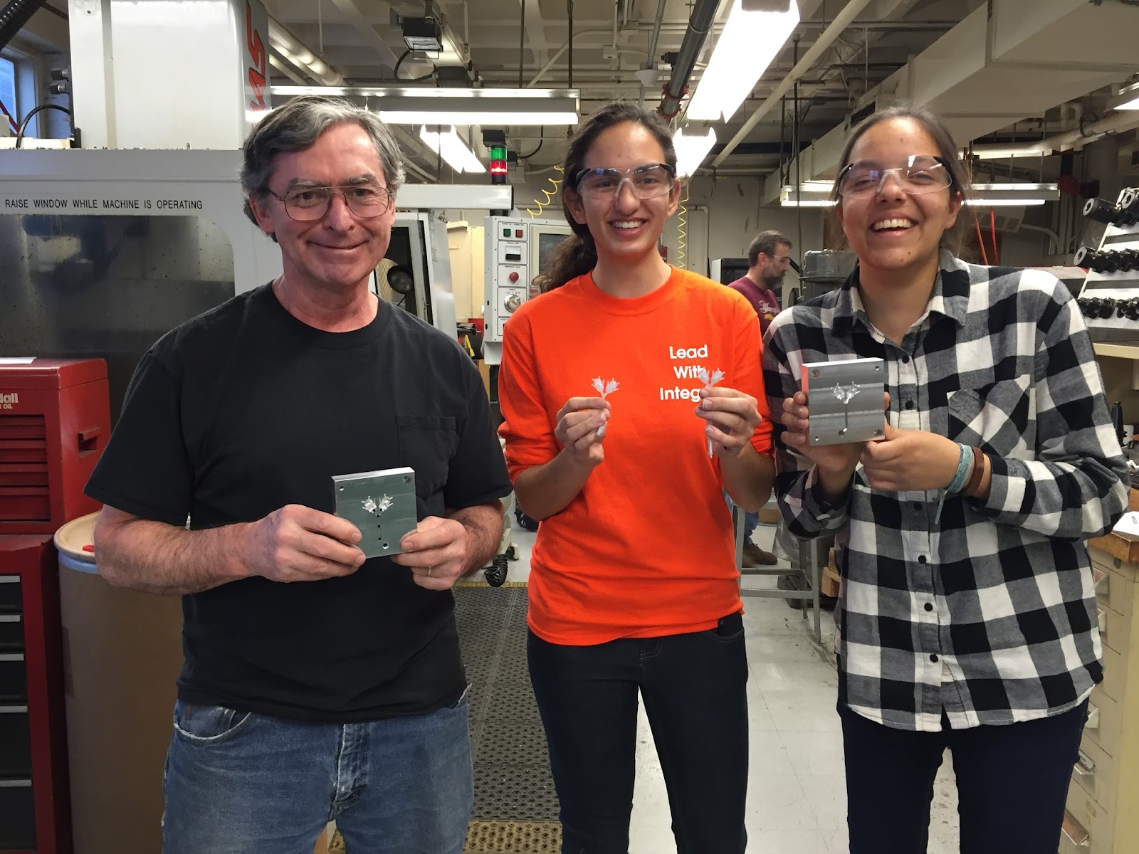
The 3D machined core and cavity molds!
Our UFO Yo-yo has three injection molded parts, a top ring, a bottom part, and an alien. For each of our injection molded parts, we have unique details with complex curves that required the use of 3D-milling in our molds each of our molds. Here we would like to talk about the details and the production of the bottom part molds and injection molding parameters in a little more depth.
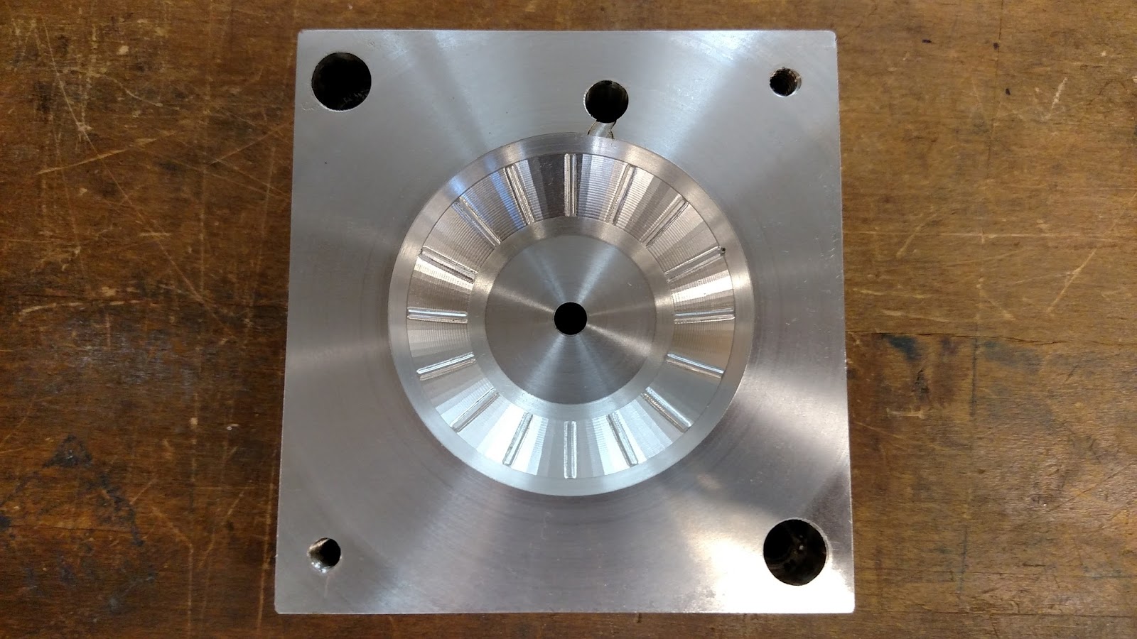
The bottom mold had both a core and a cavity, each requiring both lathe and mill work. The core mold defines the shape of both snap fits in the part, where the alien snap fits into the base and the top ring snaps in as well. It also shapes the groove where the thermoformed dome rests. The final product is shown below.
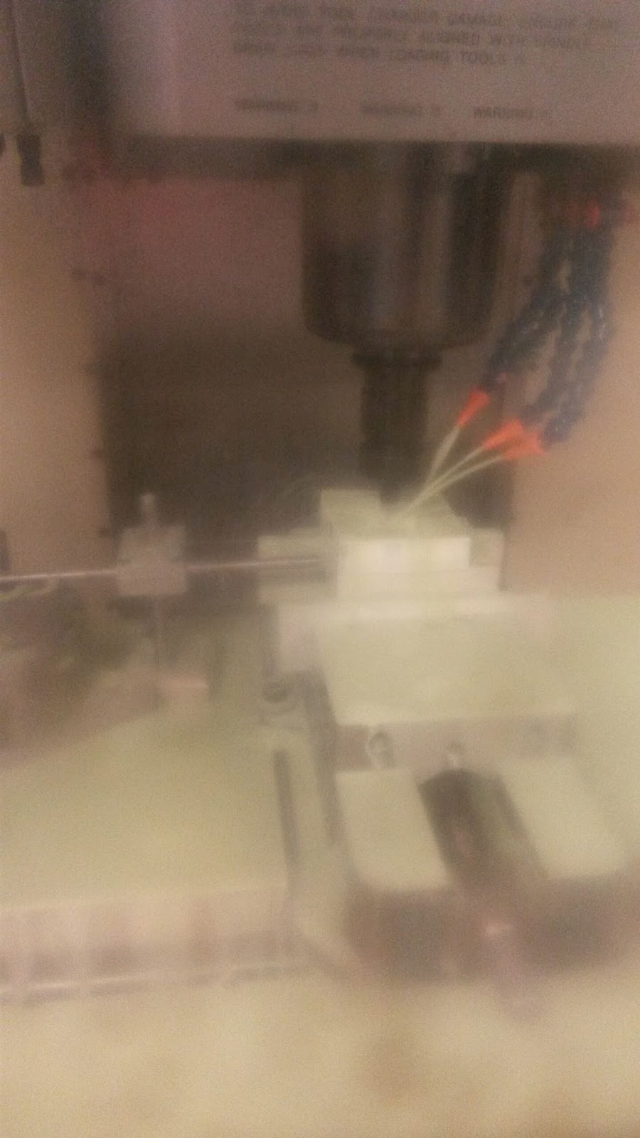
Most of the features in core mold were mostly completed on the lathe using trepanning and boring tools. The milling process added the six ejector pins on the outer edge of the flat part, and the central ejector pin. A significant portion of the milling time was taken up by the engraving of the small keys on the keyboard surrounding the alien. Initially we were considering using stickers to put the complex designs on the keyboard, but the fine engraving tool (Tool 14) allowed us to add the desired fine detail. Below is an image of the engraving process on the Protrak. The process plan for the core is also below.
Process Plan - Core
Step
|
Operation
|
Machine
|
Tool
|
Justification
|
1
|
Core - Facing Cut
|
Lathe
|
T0101
|
Facing cut to create smooth surface
|
2
|
Core - Rough Cut
|
Lathe
|
T0303
|
Remove bulk of material
|
3
|
Core - Rough Trepan
(w/ finishing pass)
|
Lathe
|
T0909
|
Define majority of core
|
4
|
Core - Boring Trepan
|
Lathe
|
T0808
|
Defining deeper, sharper features such as top part snap fit
|
5
|
Core - Facing Cut
|
Mill
|
T6
|
Shortening depth of the alien snap fit
|
6
|
Core - Center Drill
|
Mill
|
T13
|
Pilot holes for ejector pins
|
7
|
Core - Drill
|
Mill
|
T17
|
Ejector pins
|
8
|
Core Engraving
|
Mill
|
T14
|
Keyboard Features
|
The cavity mold defines the outer shape of the bottom of the UFO. The cavity mold requires time on both the mill and the lathe. The lathe work was relatively simple as it just made a curve that the 3D milling would then refine. 3D milling was then used to create some fine surface features, small curved strips on the outside of the UFO that the team thought added significant value to the part.The cavity mold after a simple turn is shown below. Also shown in this image is the shoulder bolts that allow us to place a nut into the injection molded part so that we can attach the two halves of the yo-yo together with a threaded shaft. Here, the shafts have been cut down to size so that their ends will sit flush with the end of the mold against the injection molding machine.
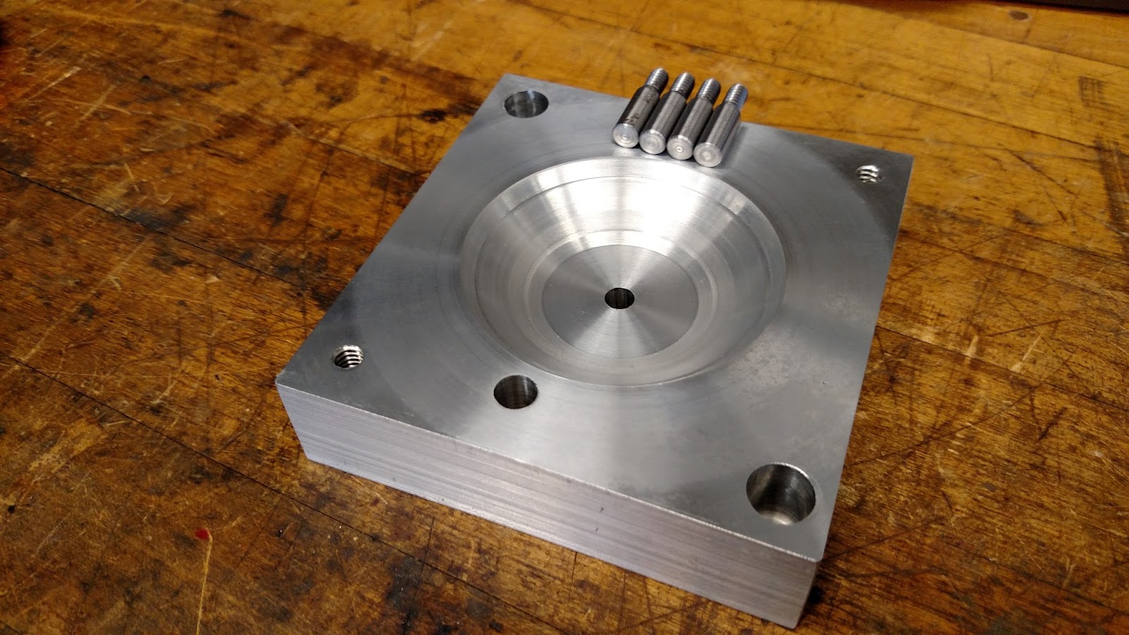
After the mold was turned, it was sent off the 3D machining! Our run time was just under 6 hours so we ran the cycle overnight. Below is our first run.
This run had three separate issues. The first was that the final finish was from the circular contours with the ⅛” ball endmill rather than with the radial passes of the 1/32” ball endmill, which would leave a much finer finish. This is likely because the part was touched off slightly too high. The second issue was that one of the strips seen here on the top right, was cut slightly too deeply around the edges. This was fixed by correcting a check surface on the Mastercam file. Finally, all of machine finish was around the strips, leaving large smooth segmented faces on the mold, while we intended to have a uniform finish.
We decided to turn the part once more and re-do the 3D machining so that we could fix each of these problems. An important note for the turning process was to leave stock on the drive surface, or the whole curved surface rather than just on the small strips that needed to be defined by 3D milling. This led to a more complete look of the mold features. Below we show the 3D machining process. The mold is completely flooded with coolant to help the 3D machining run smoothly. In addition, below is a snapshot of the Mastercam, showing the difference between the first turn, and the second turn. The slight difference in toolpath on the outer edges of the finish led to a more complete look after the second turn. These changes allowed for the smooth uniform finish shown close up below. Below is also the process plan for the cavity mold.
.

Process Plan Cavity
Step
|
Operation
|
Machine
|
Tool
|
Justification
|
1
|
Cavity - Rough Bore
|
Lathe
|
T1010
|
Remove bulk of material
|
2
|
Cavity - Finish Cut
|
Lathe
|
T0505
|
Finish Pass
|
3
|
Cavity - Center Drill
|
Lathe
|
T0404
|
Start hole for shoulder bolt
|
4
|
Cavity - Drill
|
Lathe
|
T0202
|
Drill shoulder bolt hole
|
5
|
Cavity - Surface Rough Contour
|
Mill (HAAS)
|
T9
|
Cut out bulk of shape with ⅛” ball endmill
|
6
|
Cavity - Surface Finish Radial
|
Mill (HAAS)
|
T18
|
Create radial surface finish with 1/32” ball endmill
|
7
|
Cavity - Parallel Cuts
|
Mill (HAAS)
|
T18
|
Further define strips with parallel cuts
|
8
|
Cavity - Gate
|
Mill (HAAS)
|
T3
|
Make gate with ⅛” flat endmill
|
Summary of Parameter Analysis
In our first optimization run, we changed three parameters: the shot size, the cooling time and the clamping force. Each of these were in response to clear errors we saw in the first couple parts. First we noticed significant short shot, so we increased the shot size from 2.5 in^3 to 3.4 in^3. After doing this we noticed significant flash. At first we thought the shaft may be slightly too long so we switched shafts since we had been using the same one. However, this also resulted in significant flash, so we tripled the clamping force. Finally, when handing the earlier runs, we noticed that the parts were very warm, to the point where they were difficult to handle. This, along with the fact that this is a very thick part that could have significant shrinkage as a result, led us to double the cooling time from 20 to 40 seconds. This improved our shrinkage, making our outer snap fit exactly to spec.
Further optimization is necessary to remove the minimal flash on the parts and minimize the appearance of the welding line in bottom part. We expect the flash to be improved by slightly decreasing the shot size and increasing the clamping force. We expect to decrease the appearance of the weld line in the part by changing to injection speed profile to be more similar to that in the top part, where the plastic gets injected in quickly at first and more slowly as the stroke proceeds. If this doesn’t work, we will also test an intrusion stroke.
Parameter Analysis
Part One - the shot size was 2.50, cooling time 20s, and clamping force 10
Was not nearly enough plastic to fill the part - short shot
Outer snap: 1.926in
Inner snap: 0.260in

Part Two - increased shot size to 3.40 in^3
Finished part - very bad flash about 1/2in long and 0.016in thick
Outer snap: 1.983in
Inner snap: 0.260in

Part Three - changed the shaft to see if that stopped molds from closing
Finished part - very bad flash about 1/2in long and 0.016in thick
Outer snap: 1.983in
Inner snap: 0.260in

Part Four - tripled the clamping force
Minimal Flash
Outer snap: 1.994in
Inner snap: 0.255in
Minimal Flash (looks same as part above)
Outer snap: 1.999in
inner snap: 0.257 in
Team Troubleshooting and Takeaways
As a team we came together and tested to see of our snap fits worked. The aliens fit in relatively well, and they passed a ‘drop test’, meaning they stayed in the snap fit when the bottom part and alien were dropped together. However, when testing our snap fit with the top part, there was a clearance of .009 in (a difference of .018 inches in diameter). This clearance is significant and cannot be made up by changing injection molding parameters. Since changing the top part could require us to remake the the whole core mold for the top ring, we decided to do a simple turn on the lathe and increase the snap fit diameter by .028 inches, to allow for .01 interference. This taught us that while we have defined specifications and tolerances, it is often a difficult to be sure of these numbers until testing has occurred. Additionally, we learned there is value to making the product work and possibly straying from our initial specifications, if there is sufficient leeway to do so, as there was in our case. As a team we worked well to fix the problems we faced and move our yo-yo forward!
Subscribe to:
Posts (Atom)