The 3D machined core and cavity molds!
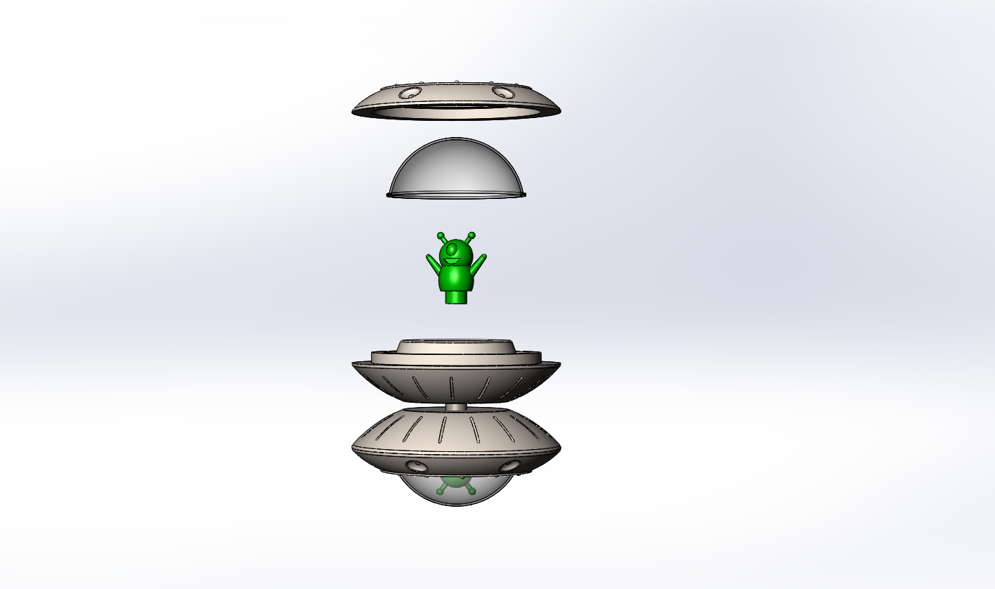
Our UFO Yo-yo has three injection molded parts, a top ring, a bottom part, and an alien. For each of our injection molded parts, we have unique details with complex curves that required the use of 3D-milling in our molds each of our molds. Here we would like to talk about the details and the production of the bottom part molds and injection molding parameters in a little more depth.
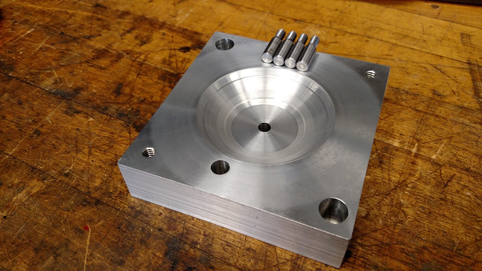
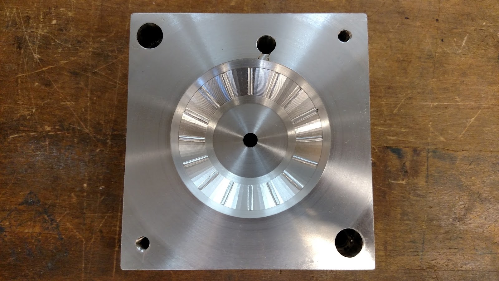
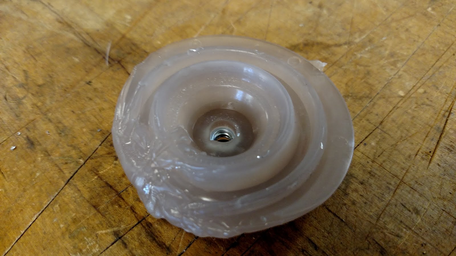
The bottom mold had both a core and a cavity, each requiring both lathe and mill work. The core mold defines the shape of both snap fits in the part, where the alien snap fits into the base and the top ring snaps in as well. It also shapes the groove where the thermoformed dome rests. The final product is shown below.
Most of the features in core mold were mostly completed on the lathe using trepanning and boring tools. The milling process added the six ejector pins on the outer edge of the flat part, and the central ejector pin. A significant portion of the milling time was taken up by the engraving of the small keys on the keyboard surrounding the alien. Initially we were considering using stickers to put the complex designs on the keyboard, but the fine engraving tool (Tool 14) allowed us to add the desired fine detail. Below is an image of the engraving process on the Protrak. The process plan for the core is also below.
Process Plan - Core
Step
|
Operation
|
Machine
|
Tool
|
Justification
|
1
|
Core - Facing Cut
|
Lathe
|
T0101
|
Facing cut to create smooth surface
|
2
|
Core - Rough Cut
|
Lathe
|
T0303
|
Remove bulk of material
|
3
|
Core - Rough Trepan
(w/ finishing pass)
|
Lathe
|
T0909
|
Define majority of core
|
4
|
Core - Boring Trepan
|
Lathe
|
T0808
|
Defining deeper, sharper features such as top part snap fit
|
5
|
Core - Facing Cut
|
Mill
|
T6
|
Shortening depth of the alien snap fit
|
6
|
Core - Center Drill
|
Mill
|
T13
|
Pilot holes for ejector pins
|
7
|
Core - Drill
|
Mill
|
T17
|
Ejector pins
|
8
|
Core Engraving
|
Mill
|
T14
|
Keyboard Features
|
The cavity mold defines the outer shape of the bottom of the UFO. The cavity mold requires time on both the mill and the lathe. The lathe work was relatively simple as it just made a curve that the 3D milling would then refine. 3D milling was then used to create some fine surface features, small curved strips on the outside of the UFO that the team thought added significant value to the part.The cavity mold after a simple turn is shown below. Also shown in this image is the shoulder bolts that allow us to place a nut into the injection molded part so that we can attach the two halves of the yo-yo together with a threaded shaft. Here, the shafts have been cut down to size so that their ends will sit flush with the end of the mold against the injection molding machine.
After the mold was turned, it was sent off the 3D machining! Our run time was just under 6 hours so we ran the cycle overnight. Below is our first run.
This run had three separate issues. The first was that the final finish was from the circular contours with the ⅛” ball endmill rather than with the radial passes of the 1/32” ball endmill, which would leave a much finer finish. This is likely because the part was touched off slightly too high. The second issue was that one of the strips seen here on the top right, was cut slightly too deeply around the edges. This was fixed by correcting a check surface on the Mastercam file. Finally, all of machine finish was around the strips, leaving large smooth segmented faces on the mold, while we intended to have a uniform finish.
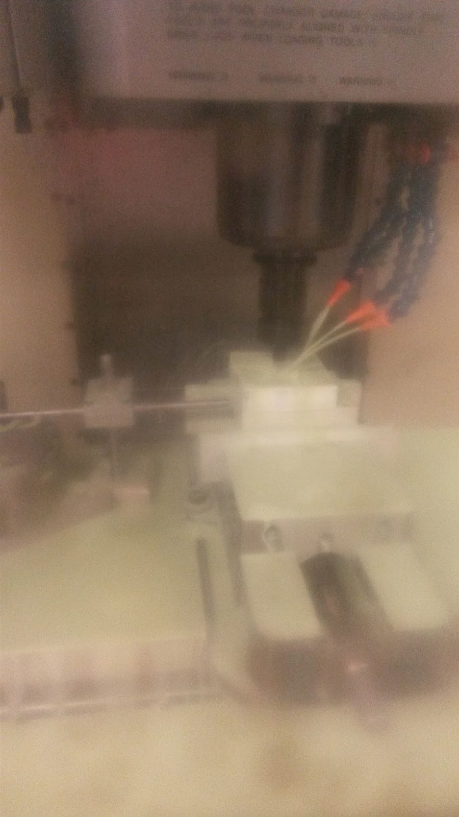
We decided to turn the part once more and re-do the 3D machining so that we could fix each of these problems. An important note for the turning process was to leave stock on the drive surface, or the whole curved surface rather than just on the small strips that needed to be defined by 3D milling. This led to a more complete look of the mold features. Below we show the 3D machining process. The mold is completely flooded with coolant to help the 3D machining run smoothly. In addition, below is a snapshot of the Mastercam, showing the difference between the first turn, and the second turn. The slight difference in toolpath on the outer edges of the finish led to a more complete look after the second turn. These changes allowed for the smooth uniform finish shown close up below. Below is also the process plan for the cavity mold.
.

Process Plan Cavity
Step
|
Operation
|
Machine
|
Tool
|
Justification
|
1
|
Cavity - Rough Bore
|
Lathe
|
T1010
|
Remove bulk of material
|
2
|
Cavity - Finish Cut
|
Lathe
|
T0505
|
Finish Pass
|
3
|
Cavity - Center Drill
|
Lathe
|
T0404
|
Start hole for shoulder bolt
|
4
|
Cavity - Drill
|
Lathe
|
T0202
|
Drill shoulder bolt hole
|
5
|
Cavity - Surface Rough Contour
|
Mill (HAAS)
|
T9
|
Cut out bulk of shape with ⅛” ball endmill
|
6
|
Cavity - Surface Finish Radial
|
Mill (HAAS)
|
T18
|
Create radial surface finish with 1/32” ball endmill
|
7
|
Cavity - Parallel Cuts
|
Mill (HAAS)
|
T18
|
Further define strips with parallel cuts
|
8
|
Cavity - Gate
|
Mill (HAAS)
|
T3
|
Make gate with ⅛” flat endmill
|
Summary of Parameter Analysis
In our first optimization run, we changed three parameters: the shot size, the cooling time and the clamping force. Each of these were in response to clear errors we saw in the first couple parts. First we noticed significant short shot, so we increased the shot size from 2.5 in^3 to 3.4 in^3. After doing this we noticed significant flash. At first we thought the shaft may be slightly too long so we switched shafts since we had been using the same one. However, this also resulted in significant flash, so we tripled the clamping force. Finally, when handing the earlier runs, we noticed that the parts were very warm, to the point where they were difficult to handle. This, along with the fact that this is a very thick part that could have significant shrinkage as a result, led us to double the cooling time from 20 to 40 seconds. This improved our shrinkage, making our outer snap fit exactly to spec.
Further optimization is necessary to remove the minimal flash on the parts and minimize the appearance of the welding line in bottom part. We expect the flash to be improved by slightly decreasing the shot size and increasing the clamping force. We expect to decrease the appearance of the weld line in the part by changing to injection speed profile to be more similar to that in the top part, where the plastic gets injected in quickly at first and more slowly as the stroke proceeds. If this doesn’t work, we will also test an intrusion stroke.
Parameter Analysis
Part One - the shot size was 2.50, cooling time 20s, and clamping force 10
Was not nearly enough plastic to fill the part - short shot
Outer snap: 1.926in
Inner snap: 0.260in

Part Two - increased shot size to 3.40 in^3
Finished part - very bad flash about 1/2in long and 0.016in thick
Outer snap: 1.983in
Inner snap: 0.260in

Part Three - changed the shaft to see if that stopped molds from closing
Finished part - very bad flash about 1/2in long and 0.016in thick
Outer snap: 1.983in
Inner snap: 0.260in

Part Four - tripled the clamping force
Minimal Flash
Outer snap: 1.994in
Inner snap: 0.255in
Minimal Flash (looks same as part above)
Outer snap: 1.999in
inner snap: 0.257 in
Team Troubleshooting and Takeaways
As a team we came together and tested to see of our snap fits worked. The aliens fit in relatively well, and they passed a ‘drop test’, meaning they stayed in the snap fit when the bottom part and alien were dropped together. However, when testing our snap fit with the top part, there was a clearance of .009 in (a difference of .018 inches in diameter). This clearance is significant and cannot be made up by changing injection molding parameters. Since changing the top part could require us to remake the the whole core mold for the top ring, we decided to do a simple turn on the lathe and increase the snap fit diameter by .028 inches, to allow for .01 interference. This taught us that while we have defined specifications and tolerances, it is often a difficult to be sure of these numbers until testing has occurred. Additionally, we learned there is value to making the product work and possibly straying from our initial specifications, if there is sufficient leeway to do so, as there was in our case. As a team we worked well to fix the problems we faced and move our yo-yo forward!
No comments:
Post a Comment